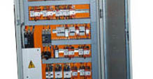
Products - Panels for OEM users - Chillers
Following are the OEM application in which Control Systems Engineers have devoted many years in development
Wind Energy / Wind Turbine Panel | Compressor Control Panel | Flare Systems | Incinerators | Evaporators |
Filtration systems | Boilers | Chillers | Spray Driers | Krom Schroder | Test / Simulation | Transfomers | HVAC Panel
Filtration systems | Boilers | Chillers | Spray Driers | Krom Schroder | Test / Simulation | Transfomers | HVAC Panel
The chiller components to be adjusted during the chiller start-up, load-flow, and shutdown procedures are
Listed ; they have the following features:
The chiller start-up command can be given through the push button on the chiller control panel or through the control software in the computer. The chiller starts the CHWP, the CWP, and the solution pump, and opens the steam valve in sequence. To operate these four major components, four conditions must be met:
- The chilled-water pump (CHWP) is a constant speed pump. It starts or stops immediately once it received an on or off command. The CHWP is usually the first component to start in the chiller and the last component to stop.
- Similar to the CHWP, the cooling-water pump (CWP) is a constant speed pump. It starts or stops immediately once it has received an on or off command. It operates only when the CHWP is running.
- The solution pump has a variable-frequency drive that adjusts the pump speed to maintain the sorbent solution level in the HTRG constant. It starts or stops immediately once an on or off command has been received.
- The refrigerant pump is a constant-speed pump. It starts or stops immediately once an on or off command is received.
- The cooling-tower fan (CTF) has low, medium, and high speeds to maintain the desired coolingwater supply temperature 105
- The steam valve has four staged openings. The steam valve opens or closes in steps between the first and fourth stages. The opening or closing of the steam valve is not measured directly but is estimated by the corresponding operating time of the drive motor.
- The city-water switch (CTS) is a magnetic valve. It opens or closes immediately once an on or off signal has been received. The CTS remains open to supply city water to the cooling tower because the cooling tower loses water to the atmosphere while the chiller operates.
- The cooling-water drain device (CWDD) is motor driven. The motor runs for a certain time to open or close the valve completely once an on or off command has been received. The cooling water begins to drain the cooling-water tank until it is empty, once the CWDD has opened for a certain length of time. When the cooling tower begins to fill with city water, the CWDD must be closed.
- The cooling-water by-pass valve (CWBPV) is motor driven. The motor runs until the valve is fully open or closed, as soon as it has received an on or off command. The cooling-water supply temperature is kept sufficiently high by the by-pass of circulating cooling water around the cooling tower.
- The electric refrigerant pump heater (RPH) prevents refrigerant from freezing in the evaporator.
The chiller start-up command can be given through the push button on the chiller control panel or through the control software in the computer. The chiller starts the CHWP, the CWP, and the solution pump, and opens the steam valve in sequence. To operate these four major components, four conditions must be met:
- ambient temperature must be higher than a preset value
- cooling-water tank must be filled with water
- chilled-water flow must be sufficient
- chilled-water supply temperature must be higher than a preset value To meet these conditions, the chiller control system needs to open or close the corresponding valves (the CWDD and the CTS). The start-up procedure is illustrated in Figure 2A-1.


